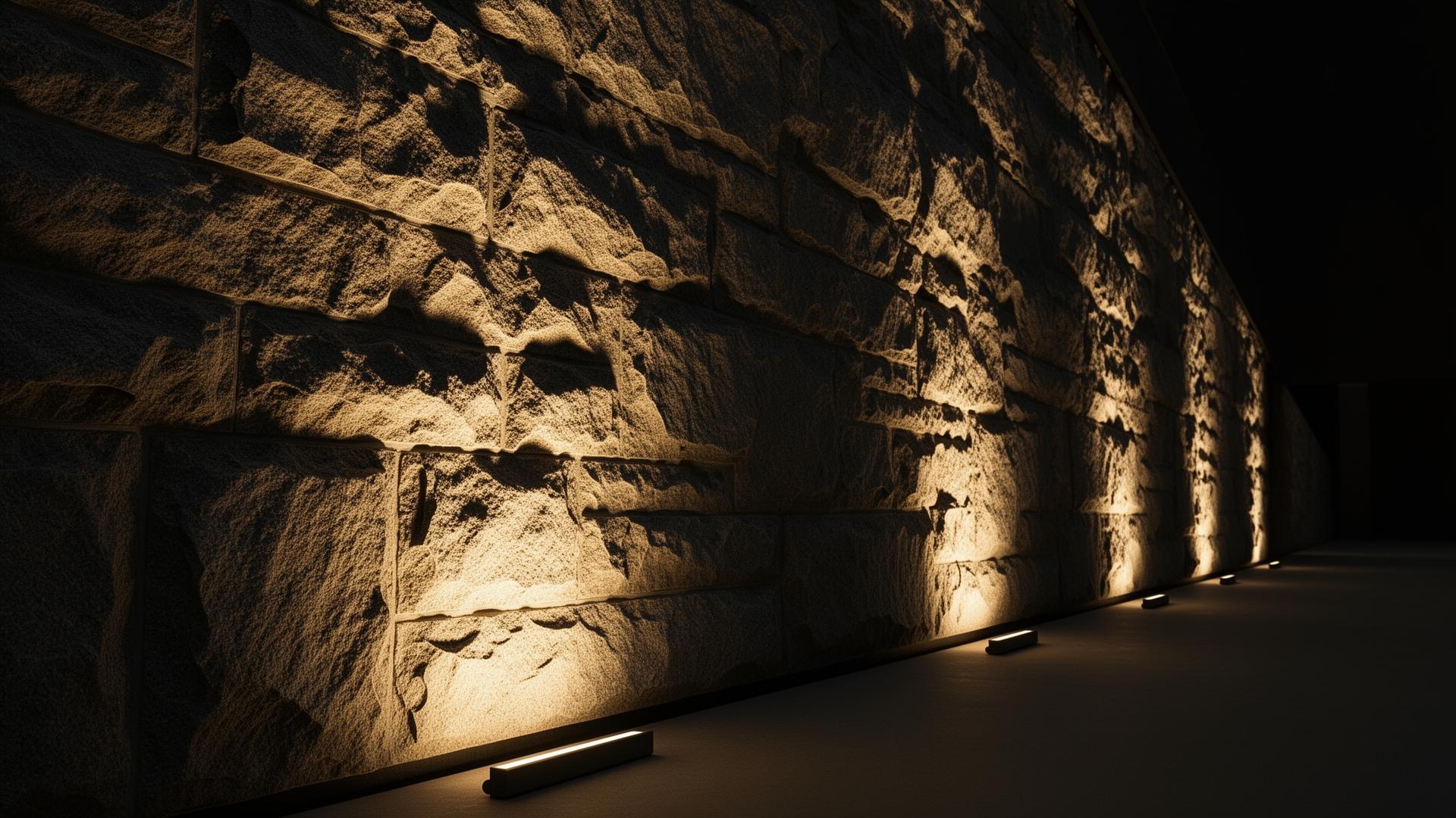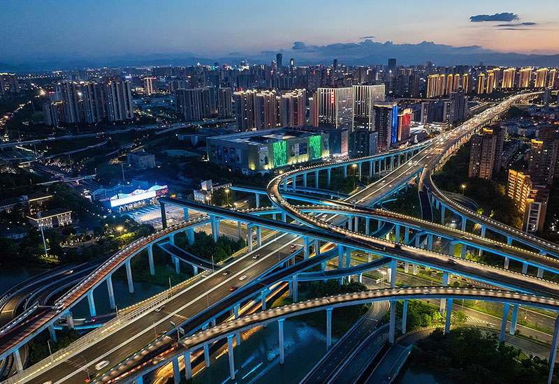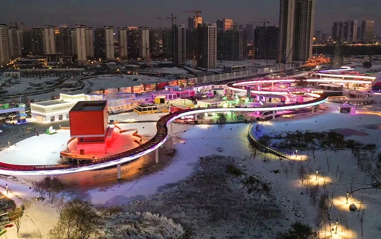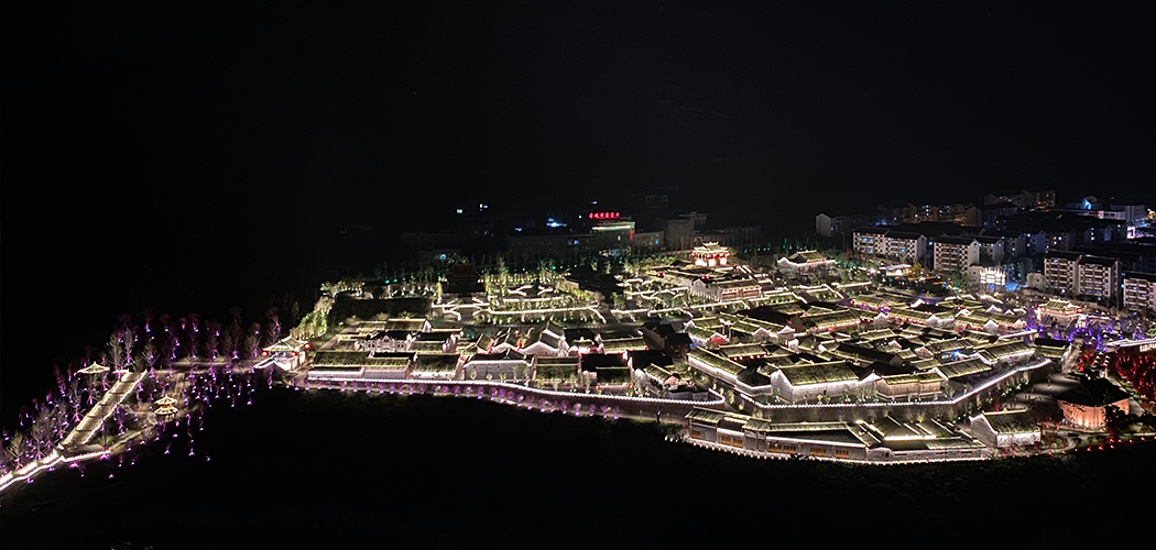


Low-voltage landscape lighting is widely used in residential gardens, hotel resorts, public parks, pathways and architectural accent lighting. Although these systems operate at a reduced voltage on the lighting side, reliable performance still depends on correct electrical design, compatible power supplies, suitable cable sizing and properly installed connections.
For landscape contractors, lighting designers, electrical engineers and procurement teams, the main challenge is not simply selecting fixtures. Long cable runs, unevenly distributed loads, unsuitable transformers and poorly sealed connections can cause inconsistent brightness, unstable color output, intermittent operation and difficult maintenance.
This guide explains how to plan a low-voltage landscape lighting system, calculate voltage drop, size transformers, select outdoor wiring and specify protection requirements for project installation and tender documentation..
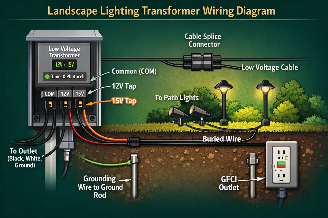
A low-voltage landscape lighting system typically uses a transformer or power supply to convert the mains supply into a lower-voltage output. The correct configuration depends on the connected fixtures and their electrical requirements.
| Design consideration | 12V AC system | 12V DC system |
|---|---|---|
| Power source | Compatible AC transformer | Compatible DC power supply |
| Fixture compatibility | Fixtures designed for the specified AC input | Fixtures designed for the specified DC input |
| Wiring | Polarity is generally not a factor for ordinary AC connections | Positive and negative polarity must be observed |
| Dimming and controls | Depends on transformer, driver and dimmer compatibility | Depends on power supply, driver and control interface |
| Common design concern | Compatibility with LED retrofit lamps and dimming equipment | Voltage drop, polarity, load limits and driver compatibility |
These configurations are not automatically interchangeable. A fixture marked for 12V AC should not be assumed to operate correctly on 12V DC, or vice versa, unless the manufacturer confirms compatibility.
For RGB and RGBW lighting, verify the complete system—including the fixture, power supply, controller, wiring and control protocol—before finalizing the design. The use of DC power alone does not guarantee smooth dimming, stable color or flicker-free performance.
Voltage drop occurs when current flows through the resistance of a cable. Because low-voltage landscape circuits operate at relatively low voltages, the same cable resistance can represent a larger percentage of the supply voltage than it would in a mains-voltage circuit.
Excessive voltage drop may cause fixtures near the end of a circuit to operate differently from those close to the power source. The actual effect depends on the fixture's input-voltage range, internal driver and control design.
The main variables are:
Cable length: Longer conductors generally produce greater resistance.
Load current: Higher current increases the voltage lost in the cable.
Conductor size: A larger conductor generally has lower resistance.
Load distribution: A circuit with many fixtures concentrated at its far end behaves differently from one with evenly distributed loads.
Operating conditions: Conductor temperature and the actual supply voltage can affect the result.
For a simple two-conductor circuit, a preliminary voltage-drop calculation can be expressed as:
Voltage drop = current × total circuit conductor resistance
For a uniform cable, total conductor resistance includes both the outgoing and return paths. More complex layouts with multiple branches should be calculated section by section, using the current carried by each section.
The percentage voltage drop is:
Voltage drop (%) = voltage drop ÷ supply voltage × 100
For example, if a 12V circuit has a calculated drop of 0.6V, the percentage drop is 5%. This is a calculation example, not a universal acceptance threshold.
The allowable drop should be specified according to the fixture's permitted input range, the required lighting uniformity and the project's design criteria. A project may adopt a 5% or 10% target, but neither figure should be treated as a universal rule for every fixture and installation.
Consider the following measures during design:
Locate the power supply where it can serve the connected lighting zones efficiently.
Divide long layouts into separate circuits or branches where appropriate.
Increase conductor size when calculations show that the proposed cable is insufficient.
Distribute loads across the circuit rather than concentrating too much load at the end.
Evaluate multi-tap AC transformers only when the fixture input range and transformer specifications permit the selected output tap.
Measure voltage at representative fixtures under normal operating load during commissioning.
A home-run or branched layout can make voltage-drop management easier, but it is not automatically superior in every installation. The final topology should reflect the site plan, cable routes, load distribution, maintenance access and cost.
Transformer selection should begin with the electrical requirements of the connected fixtures. Choosing a transformer based only on the total number of lights—or selecting one whose wattage exactly matches the nominal fixture load—can leave insufficient operating margin.
Add the rated input power of all fixtures supplied by the circuit.
For example, a circuit containing 12 fixtures rated at 5W each has a nominal connected load of:
12 × 5W = 60W
This figure is the starting point for selection. For systems with electronic drivers, multiple channels or manufacturer-specific loading restrictions, check the actual input ratings and power-supply requirements.
A preliminary design may use a 25% capacity margin, subject to confirmation against the selected equipment's requirements.
For the 60W example:
60W × 1.25 = 75W
A power supply rated at or above this calculated value may be a candidate, but it is not automatically the final selection. Confirm whether the manufacturer specifies output in watts or volt-amperes (VA), and review power factor, startup current, temperature derating, circuit protection and any restrictions on the number or type of connected fixtures.
The 25% margin is a planning example rather than a universal electrical-code requirement.
Before purchase, check:
Output voltage and whether it is AC or DC
Rated output power or VA capacity
Permitted load range and startup behavior
Dimming and control compatibility
Overload, short-circuit and thermal protection
Environmental rating and installation conditions
Applicable local approvals and wiring requirements
Large gardens, resorts and parks often benefit from dividing lighting into functional zones, such as paths, planting beds, trees, retaining walls and water features.
Separate circuits can simplify voltage-drop calculations, switching schedules, fault diagnosis and maintenance. However, the number and location of power supplies should be determined by the actual electrical layout, not by a blanket rule that every large property needs multiple transformers.
For AC systems, multi-tap transformers may help compensate for calculated cable losses when the connected fixtures permit the selected output voltage. Do not increase the tap voltage without checking the voltage that nearby fixtures will receive, especially under light-load conditions.
Outdoor landscape wiring must be suitable for its installation environment. Cable intended for indoor use should not be substituted for cable approved for the proposed outdoor or direct-burial application.
Specify cable based on the calculated current, circuit length, conductor material, permitted voltage drop and applicable installation requirements. AWG numbers are commonly used in North America; other markets may specify conductor cross-sectional area in square millimeters.
There is no single cable gauge that is correct for every run longer than 30 meters. A short, lightly loaded branch may need a different conductor size from a long branch supplying multiple high-wattage fixtures.
During installation:
Use cable rated for the intended outdoor or direct-burial conditions.
Follow the applicable rules for burial depth, mechanical protection and separation from other utilities.
Avoid sharp bends, crushing, excessive tension and abrasion against rocks or hard edges.
Keep cable routes documented and accessible for future maintenance.
Label circuits and identify branches on the as-built drawing.
Underground connections are exposed to moisture, soil conditions and possible mechanical disturbance. The connector must be suitable for the cable type, conductor size, installation environment and expected service conditions.
Use connectors specifically rated for the intended outdoor or direct-burial application. Gel-filled and heat-shrink products may be appropriate where their ratings and installation instructions match the application; neither product description alone guarantees suitability.
Before backfilling, inspect each connection and verify that conductors are properly prepared, connections are secure and seals have been completed according to the manufacturer's instructions. Avoid leaving unprotected splices underground.
For fixtures installed in wet locations, verify the complete connection arrangement—including cable glands, connectors, junction boxes and fixture entries—rather than relying only on the luminaire's IP rating.
Low-voltage lighting reduces certain electrical risks on the secondary side, but it does not eliminate the need for correctly designed mains-side protection or suitable overcurrent protection.
GFCI devices are commonly used in North American installations, while RCD terminology is used in various other markets. The applicable requirements depend on the jurisdiction, the supply arrangement, the transformer or power-supply type, the installation location and the relevant electrical code.
The project specification should distinguish between different protection functions:
Ground-fault or residual-current protection: Detects certain unintended leakage-current conditions and helps reduce electric-shock risk.
Overcurrent protection: Protects conductors and equipment against excessive current from overloads or short circuits.
Isolation and output characteristics: Must comply with the requirements applicable to the selected power supply and installation.
Environmental and mechanical protection: Helps protect cables and connections against moisture, impact and other site conditions.
Do not assume that a GFCI or RCD replaces overcurrent protection, or that every low-voltage secondary circuit has identical grounding and bonding requirements.
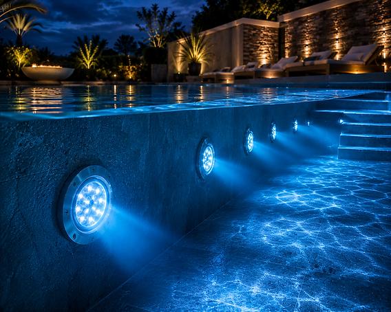
For installations near pools, fountains, ponds or other water features, the designer must assess the specific environment and applicable electrical rules. Use equipment approved for the intended location, maintain the required separation and protection measures, and have the installation reviewed by a qualified electrical professional.
Tender documents should identify the applicable jurisdiction and required code edition instead of combining requirements from different markets into a single universal rule.
A low-voltage system can still experience flicker, unstable dimming or inconsistent color if the power supply, LED driver and control equipment are incompatible.
Before specifying a dimmable landscape lighting circuit, confirm:
The permitted dimming method for the power supply and fixtures
Compatibility between the dimmer, driver and connected load
Minimum and maximum load requirements
Whether the system uses phase-cut, 0–10V, DALI, DMX or another control method
Whether color-changing fixtures require dedicated control channels
Performance at low dimming levels and during scene transitions
These interfaces are not interchangeable. For example, 0–10V and DALI generally require compatible control inputs and system architecture; they should not be assumed to work simply because a fixture operates at 12V DC. Likewise, DMX compatibility depends on the complete fixture and controller design.
For projects with cameras, color-changing effects or demanding low-level dimming, request relevant performance data or conduct an agreed test using the actual power supply, controller, fixture and operating scenes. Supply voltage alone cannot establish that a system is flicker-free.
Astronomical timers, photocells and scheduling controls can help limit operation to the hours when lighting is needed. Combine these functions with appropriate shielding, aiming and light levels to reduce unnecessary illumination. DarkSky and the Illuminating Engineering Society recommend lighting only where and when it is needed, at no greater intensity than necessary, with suitable direction and warmer color where possible. DarkSky and IES responsible outdoor lighting principles.
A useful tender specification defines the required performance and installation conditions rather than relying on general phrases such as “heavy-duty cable” or “waterproof connector.”
| Item | What the specification should define |
|---|---|
| System configuration | Required output voltage, AC or DC, and compatible fixture input |
| Connected load | Fixture quantities, rated input power and circuit load schedule |
| Voltage drop | Calculation method, design target and allowable fixture input range |
| Power supply | Rated output, capacity margin, protection, control compatibility and installation conditions |
| Cable | Conductor material and size, outdoor/direct-burial rating and route length |
| Circuit topology | Branch layout, load distribution, feed points and zoning |
| Connections | Connector type, environmental suitability and installation method |
| Electrical protection | Applicable code, ground-fault/residual-current protection and overcurrent protection |
| Controls | Dimming method, control protocol, scheduling and scene requirements |
| Commissioning | Loaded voltage measurements, functional checks and control verification |
| Handover documents | Circuit diagram, cable schedule, voltage-drop calculations, equipment datasheets and as-built drawings |
For international projects, specify the governing local code and required product approvals. Avoid assuming that one country's wiring rules automatically apply in another.
A well-designed system still needs proper installation and verification. Before handover, the project team should confirm:
The installed fixtures and power supplies match the approved submittals.
Cable sizes and routes match the design or have been recalculated after changes.
Connections and cable entries are suitable for their installation environment.
Required protective devices are installed and tested in accordance with local rules.
Voltage is measured at representative fixtures under normal operating load.
Dimming, switching, color scenes and schedules operate as intended.
Faults and deviations are recorded, and final circuit drawings are updated.
Where a project includes long runs, multiple branches or mixed fixture types, document measurements at the most electrically demanding points. This provides a useful baseline for troubleshooting future changes or maintenance issues.
It may be an appropriate project design target in some systems, but it is not a universal limit. Check the fixture's permitted input-voltage range, the required brightness consistency and the project specification before approving a circuit.
Possibly, if the total load, cable layout, output capacity and voltage-drop calculations support it. Dividing a large installation into zones can simplify control and maintenance, but the final arrangement should follow the electrical design.
Choose the configuration that matches the fixtures, power supply, dimming equipment and controls. Do not assume AC and DC versions are interchangeable without manufacturer confirmation.
There is no universal answer based on distance alone. Calculate the voltage drop using the circuit length, current, conductor resistance and load distribution, then confirm the cable's installation rating and local code requirements.
Requirements depend on the jurisdiction and the supply arrangement. The mains input, transformer or power supply, and installation environment must be assessed against the applicable electrical code by a qualified professional.
No. Dark-sky performance depends on factors such as light distribution, shielding, aiming, output level, color characteristics and operating schedules—not the supply voltage alone. Review the applicable project criteria and fixture documentation.
Reliable low-voltage landscape lighting begins with coordinated electrical and lighting design. Calculate voltage drop before selecting cable, size the transformer or power supply against the actual load and equipment requirements, specify suitable outdoor connections, and confirm electrical protection under the applicable local code.
For contractors, designers and procurement teams, a documented circuit layout, load schedule, voltage-drop calculation and commissioning record can make installation more predictable and future maintenance easier.
HIPO Lighting provides outdoor lighting solutions for architectural, landscape, roadway, tunnel and industrial applications. For landscape projects, confirm the required input voltage, control compatibility, environmental protection and supporting technical documentation for each proposed fixture before finalizing the specification.
Planning a landscape lighting project? Share your lighting layout, fixture schedule, cable-run distances and control requirements with the HIPO Lighting team to discuss product compatibility and technical selection support.